
Logic gates are the basis of computer logic. Understanding logic gate behavior is fundamental to understanding coding. A mechanical, hands-on Lego model of logic gates can help students master logic quickly.
Lego versions of logic gates often result in large and complex mechanisms. 3D printing, on the other hand, has created opportunities for small specialized mechanical logic gates. This model gives you something in-between: it's small, durable, transparent, reliable, easy to build, inexpensive, and flexible.
Ready to get started?
Design Process for a Universal Mechanical Logic Gate
Logic gates take one or more inputs and apply a set of rules to create a single output, and it's common practice to use 0 and 1 in describing logic gate inputs and outputs. Each position is called a "bit" and is capable of holding a 0 or a 1.
- 0 means off, low, empty, down, not flowing, etc.
- 1 means on, high, full, up, flowing, etc.
The simplest logic gate is what's called a "NOT" gate (also called an inverter) that takes only one input. A NOT gate simply inverts the input:

So a NOT gate just makes the output the binary opposite of the input.
Gates can be connected in series or in parallel to create more complex logic elements.
But what about logic gates that use two inputs? Yeah, that can work, too. Below are three of the six logic gates that use two inputs. The inputs on the left are labeled A and B and the resulting outputs are on the right underneath each gate name.

Each logic gate has unique behavior.
- The AND gate rule is: If A AND B are both 1, then the output is 1; otherwise, it is 0.
- The OR gate rule is: If A OR B (or both) is 1, then the output is 1; otherwise, it is 0.
- The XOR gate (exclusive OR) rule is: If only A OR B is 1 (but not both), then the output is 1; otherwise, it is 0.
Each of the above gates has a NOT version, which inverts the result. The gray-colored gates have an N for NOT added to the name, so the new gates are NAND (not AND), NOR (not OR), and XNOR (not exclusive OR). These are the other three of the six logic gates that use two inputs.

The same results (in gray) could be made by combining one AND, OR, or XOR gate with a NOT gate to invert the output.
The gray-colored gates (those inverted with NOT) are binary opposites of the first three gates. Notice each gray column has the opposite bits (zeros and ones) of the column to its left. These three "N" gates accomplish the same using one gate instead of using two gates.
The NAND gate (not AND) rule is: If A AND B are both 1, then the output is 0; otherwise, it is 1.
The NOR gate (not OR) rule is: If A OR B (or both) is 1, then the output is 0; otherwise, it is 1.
The XNOR gate (not exclusive OR) rule is: If only A OR B is 1 (but not both), then the output is 0; otherwise, it is 1.
Notice that each of the six gate output columns contains at least one 1 and one 0. Why is this? Because if you have all 0s or all 1s, there's no way to get a different result . . . so, it's not a logic gate.

Logic gates with two inputs (A & B) are usually represented as the table below: in four rows representing four input states. There are four input row combinations because there are four possible combinations of two binary inputs (00, 01, 10, 11).

So there are six two-input logic gates and two more combinations that aren't logic gates (all 0s and all 1s) for a total of eight.
- That is eight unique output columns of four bits (four rows).
- In binary, four places (2^4) are capable of representing 16 possible numbers (0 to 15).
- The eight unique gate output columns (6 valid + 2 invalid) should just need three binary bits (2^3) instead of 4 (2^4).
- There must be a pattern that can be exploited to simplify gate output rule logic.
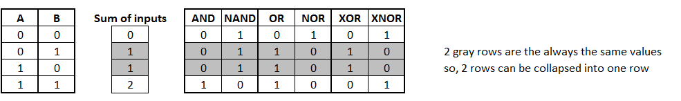
Notice the middle (gray) values are the same (per column), whether input A or input B provided the value 1. Logic gates don't know or care which input provided the 1 input value (A or B).
The addition of two binary inputs generates only three decimal sum results (0, 1, 2), instead of four row combinations (00, 01, 10, 11).
Each logic gate output can use the sum as the input, and then apply the logic rule to output 0 or 1.
There are eight possible values (0 to 7) that can be represented with 3 binary digits (000 through 111). But two of the eight values are not logic gates, because they are either all 0's or all 1's (they never change; therefore, there is no logic).

So the mechanical gate uses the three input sum combinations to model six gate outputs using three bits.
- There is only one way to have a sum of 0: Both inputs must be 0.
- There are two ways to have a sum of 1: Either A or B must be 1, but not both. But these two ways can be expressed as one row, because the logic gate doesn't care whether A or B provided the 1.
- There is only one way to have a sum of 2: both inputs must be 1.
The two middle (gray) rows above can be represented as one row (below). Using the sum of the inputs allows gate output to be represented with three rows instead of four.

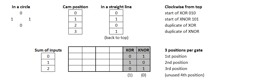
All six of the above combinations never have more than two 1s or two 0s in a sequence. These patterns can be represented in a circle (repeating) pattern with different starting points for each gate. All six logic gates can be represented in a repeating sequence of 001101. Each gate starts at a different point of the sequence and uses three sequential values.

Four logic gates can be modeled with a repeating circular cam pattern of 0011 (001, 011, 110, 100).

Two logic gates need a repeating circular cam pattern of 0101 (010, 101).
Logic-Gate Design
A compact mechanical universal logic gate needs the following:
- Mechanical motion of the output should match the motion of the input (push/pull, rotation, etc.)
- A rotating wheel with four or six positions
- Six positions allows all six gates to be modeled (001101)
- Four positions allows four gates to be modeled, but needing additional functions:
- Switch allows quick change between two circular sequences
- First sequence (0011) and second sequence (0101)
- A mechanism to stop the wheel at 1/4 or 1/6 of the rotation
- Cam lobes that rotate with the wheel shaft to raise or lower an arm
- Input lever positions that engage the wheel in passing but are not affected by wheel rotation
- Like a catalyst: input lever affects wheel; wheel cannot affect input lever
- Input levers must remain in position after they are moved
- Arm to raise or lower the output lever lifted by the rotating cams
- Some force (possibly gravity) must return output lever when cam is at 0 position
- The cams could be replaced by many different solutions such as a groved wheel with 6 lobes
- The advantage of a grooved wheel is that it wouldn't use gravity to move the output back down
This mechanical design could be easily made with 3D printing. I hope to see free designs available from our community.
Ready to build your Lego logic gates? See instructions here.