

4 Bit Binary Adder up to 15 + 15
Making a mechanical logic gate using four knob gears allows a carry to implemented coming from a lower bit. Read about the Logic Gate design here.
In this binary adder design, the first number is entered using four dark handle levers to the left of the bit place numbers. The second number is entered using the four light handle levers to the right of the numbers.
Each 24 tooth gear in the back of the binary adder has four holes. Two half pins are inserted into each gear in the back to represent a 1 or by its absence to represent a zero. On the 16 place gear to the left the pins are next to each other. All the other gears the pins are across from each other.
The cams have two angled lift arms for weight that centers the four knob gears after an action.
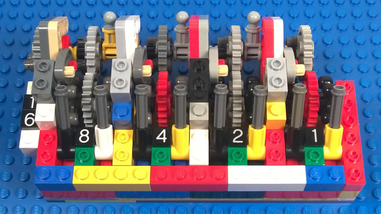
Here the binary adder is set to all zeros. The four dark handle levers (to the left of the numbers) are pushed forward. The four light handle levers (to the right of the numbers) are also pushed forward. In the back, the four tow balls are pointing up and away so it will take two 1/4 turns to activate a carry in the next binary place.

Here, the three of the dark handle levers are pulled back. The 8, 4, and 2 are back so the first number to be added is 8+4+2 = 14. Notice 3 carries have advanced a quarter turn. Two are tow balls above the 4 and 8, and the third is the 16 bit indicator that turned 1/4 turn. The half pins in the back show the first number entered is 14. The half pins are up on 8, 4, and 2 and zero on the other places.

Just to show what it would look like if three of the light handle levers are pulled back. The 8, 2, and 1 are back so the second number to be added is 8+2+1 = 11. Notice 3 carries have advanced a quarter turn. Two are tow balls above the 2 and 4, and the third is the 16 bit indicator that turned 1/4 turn. No carries have taken place yet. The half pins in the back show the second number entered is 11. The half pins are up on 8, 2, and 1 and zero on the other places.

This is what it looks like when both 14 and 11 have been added. The carries have automatically completed and the result shows in the back. The half pin is up on the 16, 8, and 1. All these bits are set so the result is 16+8+1 = 25. The half pins are down over the 4 and 2 so those bits are set to zero and aren't counted in the sum.


